





V-Page VP16K

16-Zone Intelligent Paging Station Kit

16-Zone Intelligent Paging Station Kit
  • 16 Configurable Paging Zone Button Inputs
  • 16 Indicator Outputs
  • Dante & AES67 Network Audio
  • Seamless Q-Sys Integration
  • Audio, Control, and Power over Ethernet
  • SFP Ethernet Support
  • Adjustable Mic Gain
  • Configurable LED Brightness
  • Mounts on a Standard DIN Rail
OVERVIEW

Intelligent 16-Zone Paging Station Kit

We believe that paging solutions should be a breeze to install and intuitive to operate. That’s why we designed V-Page to leverage the flexibility of industry-standard DSP platforms like Q-SYS and provide a simple button-based UI that just makes sense.

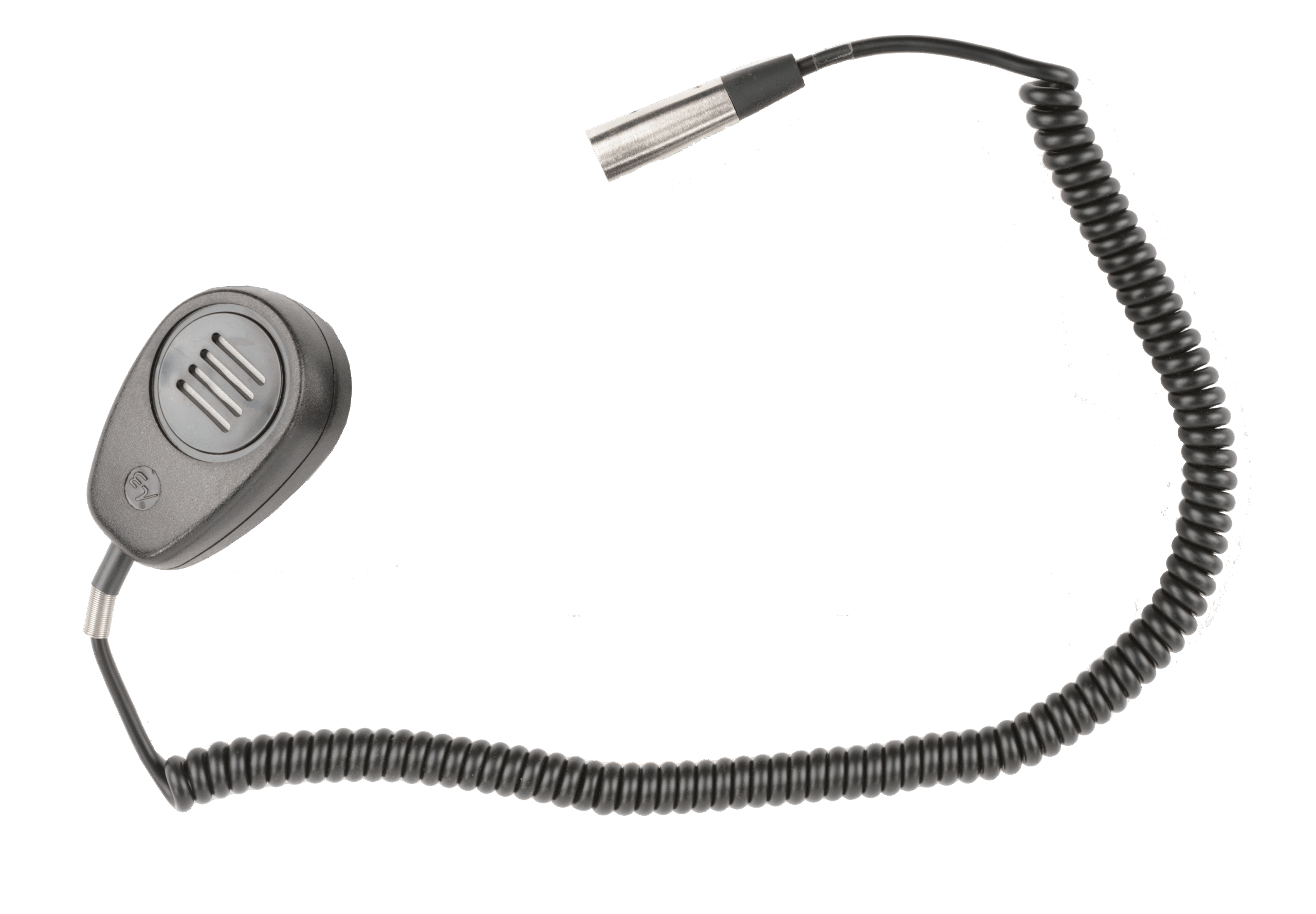
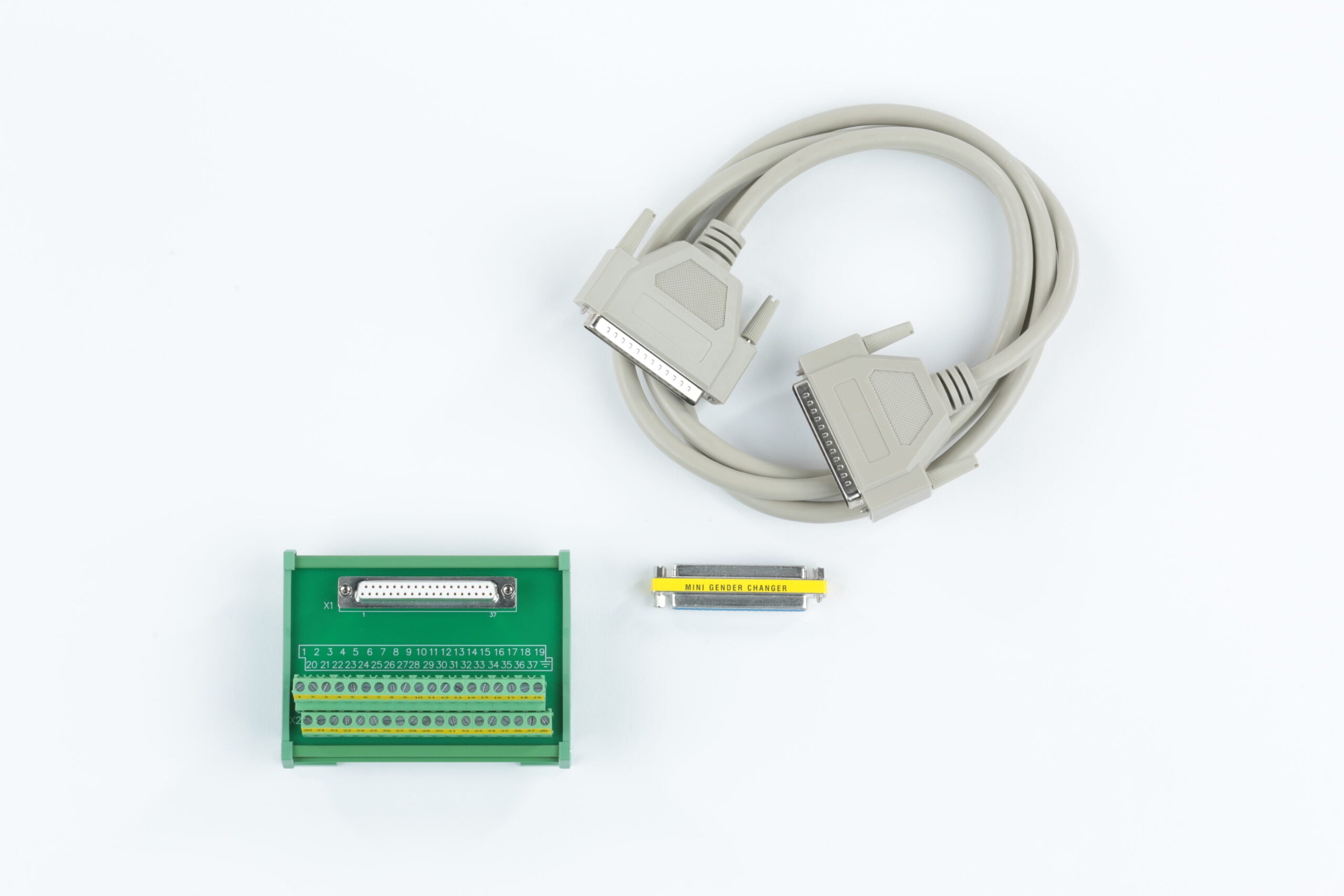
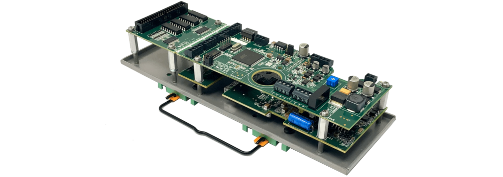
The VP16K is a paging station kit that allows you to create customized paging consoles with up to 16-zones of control. This kit is designed to mount on a standard DIN rail inside the console and comes with a panel-mount 5-pin XLR harness to interface to a microphone. The included IOBB interface allows the station to connect to up to 16-buttons and indicator LEDs.

More Ways to Configure Your VP16K

Depending on the application, you may not need all 16 channels of your VP16K, or you may need access to the SFP connection for fiber. The VP16K can be configured to accommodate both.

New VP16K units now ship with ¾” standoffs in the accessory kit. Installing these standoffs raises the PCBs to provide access to the SFP connection, making it easier to use fiber for installations where longer network distances are required.

Need something more compact? The 16-channel breakout board includes a perforated section that can be removed to create a smaller 4-channel configuration. This gives you more flexibility when installing the VP16K in smaller enclosures or tight spaces.

You don’t have to break away the board to use only four channels, either. Leave it intact if you want the flexibility to use the additional connections later, or combine the 4-channel configuration with the new standoffs when you need both a smaller footprint and SFP access.

Check out the step-by-step guide and videos below for instructions on configuring your VP16K.

Refitting for SFP Use

Need access to the SFP connection? The ¾” standoffs included in the VP16K accessory kit raise the PCBs to provide the additional clearance.

  1. Remove the 9x #4-40 screws using a P1 Phillips head driver. Keep the split lock washers and flat washers with the screws for reassembly.
  2. Remove the upper PCB. Take care not to bend the board-to-board pins during disassembly.
  3. Remove the 9x #4-40 male-female standoffs. There may be fiber washers under the 16-channel breakout board to compensate for PCB thickness.
  4. Remove the lower PCB.
  5. Install the 9x #4-40 x ¾” male-female standoffs included in the accessory kit.
  6. Reinstall the original #4-40 male-female standoffs with the fiber washers to support the wider upper PCB.
  7. Set the lower PCB into place and reinstall 5x of the #4-40 male-female standoffs.
  8. Carefully align the board-to-board pins and press the upper PCB into place.
  9. Reinstall the 9x #4-40 screws using a P1 Phillips head driver. Torque to a minimum of 4 in-lbs.


Refitting for a 4-Channel Configuration

Need a smaller footprint? The VP16K breakout board is perforated so the unused portion can be removed for more compact installations.

Note: Breaking away the PCB is permanent. If you only need four channels but may want to use the additional connections later, leave the full board intact.

  1. Remove the 4x #4-40 screws using a P1 Phillips head driver. Discard the screws, split lock washers, and flat washers.
  2. Remove the 2x M4x10mm black screws from the back of the unit using a P2 Phillips head driver. Discard the screws.
  3. Slide the secondary support out from behind the PCB and discard it.
  4. Locate the perforated section of the PCB indicated by the divots.
  5. Carefully bend the board along the perforation until the excess section snaps away. Discard the removed section.


Refitting for a 4-Channel Configuration with SFP

Need both a smaller footprint and access to the SFP connection? The VP16K can be configured for both.

  1. Remove the 9x #4-40 screws using a P1 Phillips head driver. Keep 5x screws with their split lock washers and flat washers for reassembly. The remaining 4x can be discarded.
  2. Locate the perforated section of the PCB indicated by the divots. Carefully bend the board along the perforation until the excess section snaps away and discard it.
  3. Remove the 2x M4x10mm black screws from the back of the unit using a P2 Phillips head driver. Discard the screws.
  4. Slide the secondary support out from behind the PCB and discard it.
  5. Remove the 5x #4-40 male-female standoffs.
  6. Remove the lower PCB.
  7. Install the 5x #4-40 x ¾” male-female standoffs included in the accessory kit.
  8. Set the lower PCB into place and reinstall the 5x #4-40 male-female standoffs.
  9. Carefully align the board-to-board pins and press the upper PCB into place.
  10. Reinstall the 5x #4-40 screws using a P1 Phillips head driver. Torque to a minimum of 4 in-lbs.
SOFTWARE
V-Page + V-Com Utilites
Configuration and Test Utility for V-Page and V-Com units
Release Notes
Firmware

If you’re using an older version of Q-Sys, be sure to download a release that is compatible with that platform:

  • Q-Sys v8 – v2.12+
  • Q-Sys v7 – v2.00-v2.11
  • Q-Sys v6 – v1.XX
V-Page
Firmware and Plugin for V-Page stations

Release Notes