Products Designed for Themed Entertainment
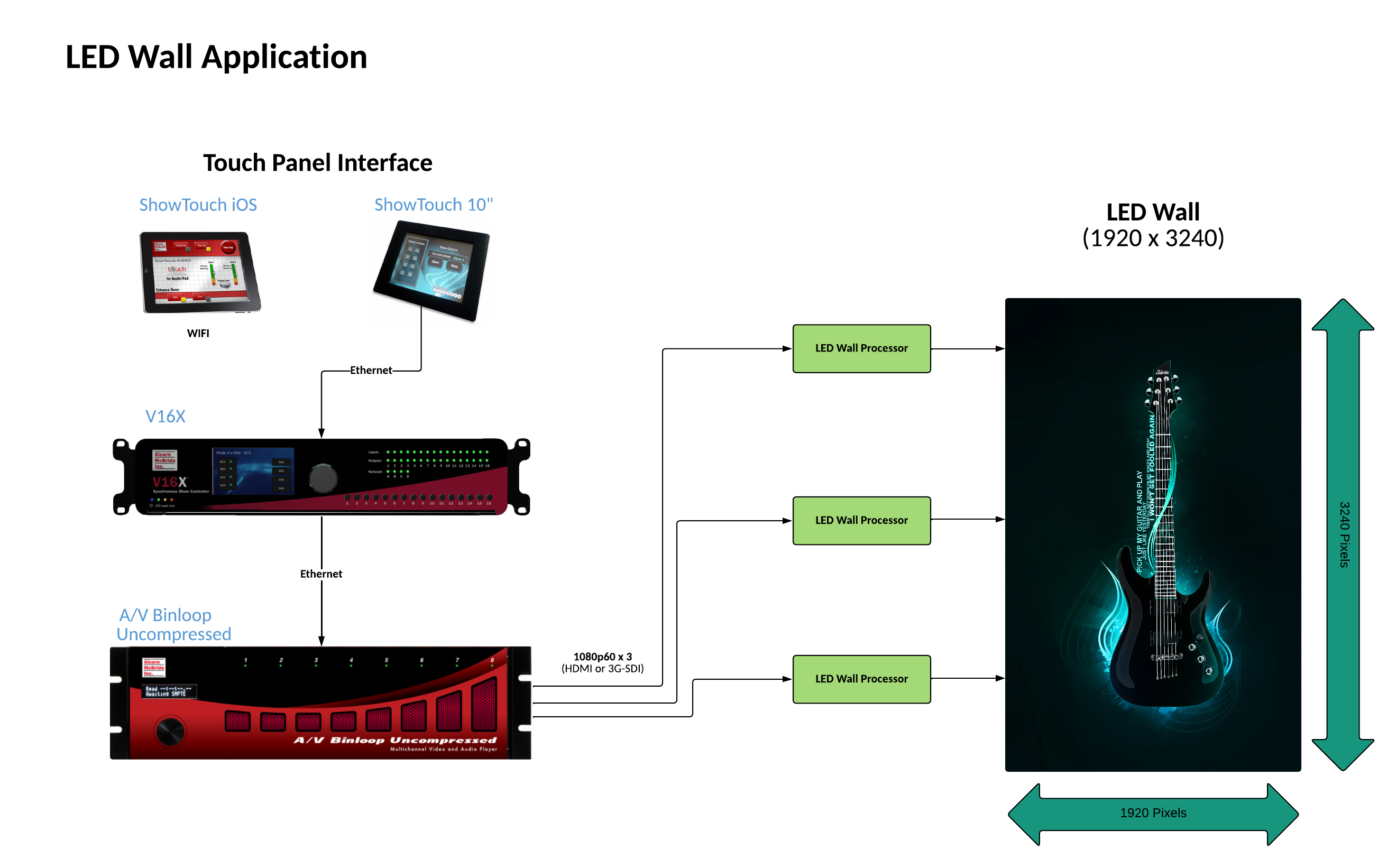

LED wall technology is advancing at an incredible rate; offering finer pixel pitch and higher resolutions. With this emerging trend, it is not uncommon for LED walls to reach resolutions of 4K, 8K, or higher. The scalable nature, high framerate capability, and superb quality of the AV Binloop Uncompressed makes it the ideal solution for these applications. As a multi-channel uncompressed player with true Genlock capability, you can add as many channels as you need to fill the native resolution of any LED wall. With the solid-state reliability of Alcorn McBride’s design, these channels will play in perfect synchronization every time for years with zero maintenance. When you add the flexibility of an Alcorn McBride V16X show controller and our ShowTouch panels, you can provide operators with easy touch panel control, scheduling, and monitoring of the system.
