Using the A/V Binloop HD to feed high-quality content to any video wall.
Introduction
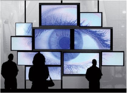 With the rapid expansion of flat-panel and LED wall technology, video walls are so ubiquitous that they have become a common part of modern architecture. They are often used to display content like video art, advertisements, promotional videos, and much more.
A typical video wall consists of multiple panels that must each be provided with their own video source. The tricky part is that those video sources must by synchronized with one another to form a coherent image across multiple panels. This is not something that can be achieved by your everyday set-top box or DVD/Blu-Ray player. It requires specialized A/V gear that is designed to provide multiple video outputs that are synchronous with one another.
There are many video wall solutions on the market that can take a single source of video and scale it across multiple displays to form a larger coherent image. However, the problem with this approach is that display resolution is wasted by the scaling process. To illustrate, imagine that you have a 2×2 configuration of 1080p (1920 x 1080 pixels) displays.
Combined, these displays have a total resolution of 3840 x 2160 pixels. However, if a 1080p (1920 x 1080) source video is used with a video wall controller, 75% of the available resolution is wasted when this material is scaled and stretched across all 4 displays. Simply enlarging the 1080p source content does not increase its resolution. The more it’s stretched, the more display resolution is wasted. Imagine how much worse this problem would be if you had a 9×9 wall…1×20 wall…etc.
This is a situation where the AV Binloop HD and its advanced capability to play synchronized video can help. Why sacrifice resolution by enlarging a single video source when you can feed each display its own video source and synchronize them? Not only does this method spare you the expense of buying a video wall controller, it takes full advantage of the display resolution and provides a crisp coherent presentation that can easily adapt to any display configuration.
This application note demonstrates how to use the A/V Binloop HD and supporting Alcorn McBride gear to implement any video wall.
Let’s Build a Video Wall!
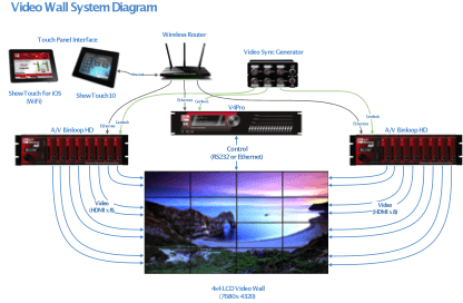
To clearly demonstrate the advantages that Alcorn McBride Show Control and the A/V Binloop HD bring to video wall systems, we will implement a 4×4 LCD video wall in this application. Assuming that 1080p flat-panels are used to build the wall, this creates a total  resolution of 7680×4320. Rather than stretch a low-res image to fill this resolution, we’re going to use the AV Binloop HD to provide 16 individual 1080p sources to feed the wall with native resolution content. Furthermore, we are going to add flexibility to the system by adding a V4Pro show controller and some of our ShowTouch panels.
The diagram below shows how this system would be implemented using actual equipment:
System Components
Let’s take a moment to walk through each component and its role in the video wall system.
A/V BINLOOP HD – MULTI-CHANNEL SYNCHRONOUS VIDEO PLAYER
The purpose of the Binloop units is to provide 16 perfectly synchronized channels of content playback. A single unit is capable of providing 8 playback channels so we must combine two units to fill the entire wall. These units play high-quality MPEG2/H264 encoded content and have hardware design features that allow it to do this with perfect frame-accurate synchronization between channels. The ability to accept an external genlock reference allows this synchronization capability to expand beyond a single Binloop to achieve as many channels as the application requires.
V4PRO – SHOW CONTROLLER
The V4Pro is the brain of the system. This product is a fully-programmable control system that is capable of remotely controlling equipment like video players, LCD panels, audio DSPs, projectors, lighting systems, or pretty much anything with a serial or Ethernet port and remote control capability.
In this system, the V4Pro is responsible for triggering both Binloops simultaneously so that the entire presentation is perfectly synchronous on all 16 LCD panels. As some other side benefits, the V4Pro is also connected to the LCD panels themselves so that it can power them on and off based on a programmed schedule. You’ll also notice several ShowTouch touch panels which are intended to give users the ability to control the wall using a customized graphical interface. Perhaps they want to launch a special presentation when a client enters their lobby or display the company logo during a photo opportunity. The V4Pro provides this kind of flexibility and much more.
SHOWTOUCH – TOUCH PANEL INTERFACE
These devices work in conjunction with the V4Pro to provide a customizable touch panel interface for users. This interface can be designed to be as simple or as complex as the application requires and can provide the ability to control the system as well as monitor status. You can use custom graphics to suit the client, like corporate logos, graphics, and color themes.
ShowTouch can run on various hardware platforms which include our ShowTouch panels (available in 7”, 10”, and 17”), iPads, iPhones, as well as any Windows-based PC.
Video Sync Generator
Since this application requires more than one AV Binloop HD, it is very important that we ensure they synchronize perfectly with one another. Thankfully, the AV Binloop HD has been designed to accept and external Genlock input for this purpose. Connecting the video sync generator to the genlock inputs of both Binloop units ensures that they play at the exact same rate with drifting from one another.
Furthermore, the timing of the control commands emanating from the V4Pro is also critical. These commands must be issued synchronously with video sync timing to ensure that playback starts at the exact same moment on both Binloops. The V4Pro is able to achieve this level of precision because it also has a genlock input.
Wireless Router
This component is simply providing a network so that all of these devices can communicate with one another. Also, it is necessary to provide Wi-Fi capability for devices that do not have hard-wired Ethernet ports like the iPad and iPhone.
Content Creation
From a content creation standpoint, the Binloop is quite simple to understand. Each channel is connected directly to dedicated LCD flat-panel. Any video content encoded and stored on a channel is what will play on the video output of that channel.
In this 4×4 video wall application, we need 16 pieces of 1080p (1920×1080) to fill the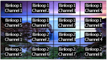 complete 7680×4320 canvas of the video wall. That means that the content needs to be divided and stored on the individual Binloop channels as demonstrated in the diagram on the right.
File Naming
When it comes to playback control, the Binloop uses a file numbering convention to identify and play files. For example, if we send the control message “Play File #1 on All Channels” to the Binloop it will analyze the files on the storage media to find the file that is properly named to be file #1. The file number is determined by a 5-digit number at the end of the file name. Here’s an example:
B1C1_CompanyLogo_00001.mpg
As you can see, the file name ends with “00001” which the Binloop identifies as being file #1. Any text located before these numeric digits is completely optional and can be anything you want. For the sake of organization, the example above uses this text to provide a nice description of the file. For example, “B1C1” indicates that this file was created for Channel 1 of Binloop 1. “CompanyLogo” is a description of the clip itself. This text has no functional meaning to the Binloop, but it sure is nice for helping a user to identify the clip at a glance.
When synchronizing clips between multiple channels, the most ideal practice is to keep the file numbers the same for each presentation. For example, if we were creating a “Company Logo” video that spanned across all 16 channels it would be best to name them like so:
B1C1_CompanyLogo_00001.mpg
B1C2_CompanyLogo_00001.mpg
B1C3_CompanyLogo_00001.mpg
Etc…
Another set of video files for a different presentation might look something like this:
B1C1_ToothpasteAd_00002.mpg
B1C2_ToothpasteAd_00002.mpg
B1C3_ToothpasteAd_00002.mpg
Etc…
When the files are named properly like this, all we have to do is tell the Binloop to “Play File 1” or “Play File 2” to trigger the different presentations.
Implementing Control
Control is an essential part of this system design. It is required to provide users with a touch panel interface so they can control the system, and it is necessary to control the various components of the system (Binloops, LCD panels, etc.) in an automated fashion.
As demonstrated in the system diagram, we will be using a V4Pro to provide the control for the entire system. It will operate in conjunction with ShowTouch panels to provide the touch panel interface. Both the V4Pro and the ShowTouch devices are configured and programmed using our WinScript Live software.
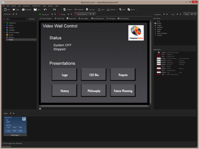
Touch Panel Design
WinScript Live is a powerful tool for creating customized touch panel interfaces that can be deployed on ShowTouch enabled devices. Its flexibility allows you to cater the look and feel of controls and status readouts to suit the needs of the application. For our 4×4 video wall application, we want to provide something that is designed to be operated by a receptionist or tour guide to provide simple one-button control to switch between different presentations.
Show Control Programming
To provide the flexibility required by various applications, the V4Pro show controller is a fully-programmable device. Using the WinScript Live software, we must configure the V4Pro so that it is aware of the devices that it will be controlling and the type of interface it will use to control them (i.e. RS232, RS422, MIDI, Ethernet, etc.). The comprehensive library of devices supported by the V4Pro is constantly updated to make this as easy as possible.
In this video wall application, we must configure the V4Pro to communicate with the Binloops and the LCD panels. We must also create programming to trigger the various presentations when buttons are pressed on the touch panel.
Although Alcorn McBride goes through great effort to make this programming significantly easier than many other control systems, there is a learning curve to using WinScript Live and the V4Pro. If you’re looking to learn more about using this interface, Alcorn McBride offers free training in the form of interactive in-person classes and online courses.
Script Overview
For this example, we will be using the same WinScript Live project that contains the ShowTouch panel. This script file is called VideoWallExample.WS4.
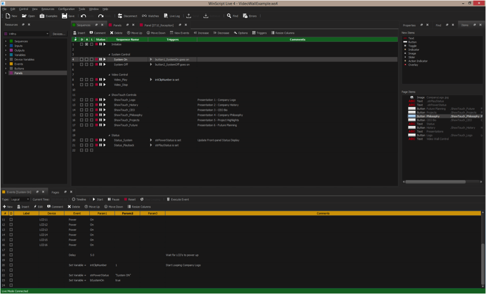
The script starts off with an ‘Initialize’ Sequence which does nothing more that initialize the front-panel display of the V4Pro.
Then we have our System_On and System_Off sequences. System_On turns on the LCD panels, waits for them to power up, and then triggers the default video presentation (corporate logo). System_Off turns off the panels and stops playback.
The Video_Play sequence will synchronously start playback on both Binloop units. It is triggered whenever the intClipNumber variable is changed.
Next, we have the sequences that are associated with ShowTouch buttons. When a button is pressed, the sequence launches and then sets the inClipNumber variable. The resulting variable change causes the Video_Play sequence to play the appropriate presentation.
Last we have a few sequences dedicated to updating the front-panel display when status information changes.
Aside from this, there is some simple logic in this script to prevent presentations from being triggered when the system is in the OFF state.
Conclusion
This application note can serve as a starting point in implementing your own video wall. Keep in mind that this design can easily be scaled up or down depending on the channel count. The V4Pro can manage more Binloop units to increase channel count. Simply connect these additional Binloops to the network and video sync generator as needed. Another thing to keep in mind is that the video sync generator is only required if you use two or more Binloops. If you use a single Binloop cage, it is perfectly capable of maintaining synchronization internally.
Now it’s time for you to make your own video wall with the Binloop HD. Please don’t forget that we are here to help you. You can download a copy of the VideoWallExample.WS4 project file mentioned in this application note here:
https://alcorn.com/Software-Uploads/VideoWallExample.ws4
You are welcome to contact us anytime at [email protected] or 407-296-5800.
Enjoy!